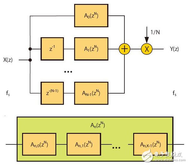
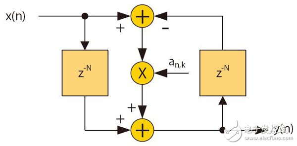
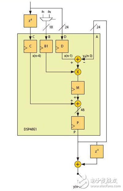
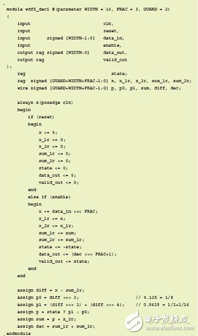
Easily create high-order polyphase IIR filters suitable for implementation in DSP48E1Slice or logic with very low resources. Designers often choose finite impulse response (FIR) filters for their applications, because such filters are easy to understand and are supported by excellent design and IP implementation tools. The Xilinx FIR Compiler is an ideal tool for mapping MATLAB® generated coefficients into DSP and FPGA logic resources. However, it is feasible to design an infinite impulse response (IIR) filter that meets the requirements of a particular filter specification while significantly reducing FPGA resource usage. The main drawback of choosing an IIR filter is that you need to master some of the expertise when using the design tool. Usually you need to manually write the RTL code later. But as long as you complete the architectural design of the filter and express it in a fixed-point manner, you can automatically generate HDL for you using a new tool like Xilinx System Generator. A series of related white papers from Xilinx provide a comprehensive introduction to various traditional IIR filters [1]. Now let's look at how to implement a high performance polyphase IIR filter with very low FPGA resources. These filter structures are characterized in that the NK+1 order filter can be realized by only K times of multiplication. Such filters have low sensitivity to coefficient quantization and can be effectively implemented in a fixed point manner. In addition, the maximum gain of any node on the filter stage is bounded, ie the intermediate calculation requires only 1 bit margin. Here we provide a generic architecture suitable for pipelining and mapping to the DSP48E1Slice in Xilinx 7 Series devices. The architecture includes a number of multiplier-free fifth-order elliptic filter designs for efficient multiphase interpolation and decimation in a small number of FPGA slices. MATLAB is able to decompose the IIR filter design into lower class combinations. This lower class association has more desirable numerical characteristics than the direct implementation of higher order difference equations. In general, the low-order filter uses a second-order double quadrant (SOS), which uses a direct-type 1 structure. Each SOS needs to complete four multiplications, three additions, and partial rounding to reduce the bit width for the next filter in the incoming cascade. For fixed-point implementations, you also need to add a multiplier to achieve inter-segment scaling. However, the cascade decomposition method is not an effective architecture for the interpolator or the decimator because it does not play the role of polyphase decomposition. For example, in the interpolation process, before applying the input data to the filter, it is necessary to insert N-1 zeros between the samples to achieve upsampling of the input data and increase the input sampling rate to be equal to the output sampling rate. However, due to the feedback path existing in each SOS, the cascaded IIR filter cannot reduce the amount of calculation by inserting zero. IIR Filters for Polyphase Decomposition The filters described herein employ the parallel filter decomposition architecture shown in Figure 1. In parallel mode, the filter on each branch is delayed by one more than the previous branch. In addition, the filter in each branch is limited to N bands. The number of delays per branch is determined by the input/output sampling rate, but the term of each An(zN) filter involves only the zN power, which means that the difference equation only computes for every Nth input/output sample, but All samples between are ignored. The transfer function is the sum of the delayed N-band all-pass filters An(zN). which is: In addition, each of the all-pass filters can be expressed as a cascade of substantially all-pass segments, as shown in FIG. Let the total number of segments of the all-pass segment be K, then the order of H(z) is NK+1. That is: Figure 1: The above is a parallel form of the IIR filter; the following is each branch consisting of a cascaded basic filter. Figure 2 is a basic all-pass segment implemented in Direct Type 1. It consists of two N-sample delay elements and a single coefficient multiplier. In addition to facilitating the use of standard multipliers, there are other advantages to using Direct Type 1. It efficiently maps to DSPSlice and shares latency resources under cascading conditions. Figure 2: Basic all-pass segment Interpolation and decimation This filter architecture can be naturally mapped into the decimation and interpolation structures shown in Figure 3. Here, the commutation switch is used to switch to each sample at a higher sampling rate, replacing the delay element used in Figure 1. For N-interpolation and decimation operations, we can either design around the ideal structure provided in Figure 3 or design a cascade consisting of prime factor sampling rate conversion. Decomposition into a prime factor [2] simplifies the coefficient optimization problem because the number of free variables is small and the resulting filter cascade is very close to the ideal state. In many applications, the required sample rate is converted to a power of two, which can be achieved by iteratively interpolating or decimation. In order not to lose the universality, let us first verify the special case when N=2. According to FIG. 3, the total order of the low pass filter is 5 when N=2, although it consists of two second-order all-pass segments and one delay element. It should now be clear that this example requires only two multipliers and five adders in this case compared to the ten multipliers and eight adders required to implement the fifth-order IIR filter using SOS. A greater degree of savings can be achieved if one considers that it is an interval 2 extraction, ie only one branch per active sample is active. This is equivalent to dividing the input sequence into two half-sample rate sequences, which are odd-numbered samples and even-order samples. These samples are then applied to the Allpass branch and summed. In addition, the delay elements in each basic segment can be run at a lower rate, halving storage requirements. This design can be efficiently pipelined and mapped to a DSPSlice because the output filters of the two branches can be accumulated using an external adder. So to implement a fifth-order, 2-decimated IIR filter as shown in Figure 4, only one DSP48E1Slice is needed. A similar situation exists for interpolation, in which a sample of an interleaver is provided in turn by each branch filter. In addition, only one DSPSlice is required to support the interpolated interpolation. The A, B, C, D, and P ports are based on the Xilinx 7 series nomenclature [3]. You can cascade DSPSlice to implement higher order filters, and because of the dual branch structure, the pipeline delay for each branch is equal. Note that because the feedback path can only be delayed by 2, DSPSlice, which requires three internal registers, cannot be fully pipelined. Using the M register allows operation at higher frequencies and consumes less power than registering at the input. When N=3 or greater, you can either use DSPSlice to run at the maximum frequency or use DSPSlice to maximize pipelining. The latter can be achieved by having the filter operate in dual-channel TDM mode, where the number of delay elements is doubled, and the A-input feedback path uses registers A1 and A2 in Slice, so that the delay before C input is increased from 3 to 5. . Figure 3: Extraction (left) and interpolation (right) Figure 4: Extracted by 2, mapped to the Xilinx DSP48E1 Quantization and Margins These N-band structures have been named Wave Digital Filters (WDF) because they can simulate double-ended lossless ladder networks in classical analog filters. A comprehensive introduction to such filter designs with elliptical responses is provided in the literature. This design, combined with a bilinear transformation for analog and digital inter-domain conversion, provides a powerful method for designing digital elliptical filters and Butterworth filters. Another advantage of using a ladder filter is that such a structure follows the low sensitivity to coefficient quantization. This means that a filter that satisfies the 100 dB stop band requirement is implemented without ripple characteristics such as degradation, and the coefficient is more than 18 bits long. Analysis of the steady-state gain characteristics of the basic segment [4] shows that the maximum gain of the arithmetic node with the lowest gain is 2.0 and occurs at the output of the pre-adder. This has a significant meaning for fixed-point design because it means we only need to add 1 bit to the pre-adder output. The pre-adder output in the Xilinx DSP48E1Slice has no saturation logic present, so limiting the output of A and D to 24 bits prevents digital overflow of the filter operation and, more importantly, allows the run to reach DSPSlice's maximum. Internal precision. Although the steady-state gain is limited to 2.0, the transient under the step response will exceed 2.0, so it is recommended to use only 23 bits to allow margin for safe operation. For some data sources, such as 24-bit music, you can apply the full dynamic range with pre-known signal characteristics. If the input data is less than 24 bits, it should be left-aligned in the word, so a partial score bit will be generated. For example, for 16-bit input data, the ideal choice is to leave 1 bit of protection bits, 16 bits of data bits, and 7 bits of fractional bits. Compared to floating point, generally only 3 to 4 fractional bits are needed to achieve the desired accuracy. Figure 5: 21st-order FIR filter and fifth-order WDF that meet the same stopband (left) and passband (right) specifications Generating filter coefficients In half-band WDF, the stop band and pass band ripple are not independent of each other. However, negligible passband ripple can be obtained by properly setting the stopband attenuation. For example, the passband ripple of the filter in Figure 5 is 10-6 dB. The advantage of FIR is that the two design parameters can be set individually so that at the given order, higher passband ripple can be set to help meet the stopband requirements. Next, let's verify what would happen if the DSP48E1 was not used, but the filter was implemented in partial LE by a high degree of quantization. Recall that since the WDF filter is based on an analog ladder filter prototype, we should be able to find the low bit density factor for a particular passband. Bits should be written as standard as possible, minimizing the number of adders, as shown in Table 1. Table 1 - Quantization coefficients for the three sample passbands Although the stop-band attenuation of the 0.19 passband's fifth-order filter is good, a simple cascade of two such filters yields a 10th-order filter with a stop-band of -78dB. For example, the first decimator in Table 1 can be implemented with a few lines of Verilog code as given in Figure 6. Figure 6: The Verilog code that implements the first decimation filter in Table 1. Effective Resources We have shown IIR filter construction that is naturally mapped into interpolation and decimation. This structure has more effective resources than the IIR II stage and even the FIR. It is fully mapped to the pre-adder/multiplier/post-adder of the DSP48E1Slice and is robust to the fixed-point quantization effect of the 18-bit coefficients, giving a controllable 100dB stopband. Some multiplier-free fifth-order designs allow for a specific pass bandwidth, which can be mapped to some logical registers and adders to reduce DSP resource usage. references: Poster Display,Led Poster Display,Indoor Led Advertising,Advertising Poster Screen APIO ELECTRONIC CO.,LTD , https://www.displayapio.com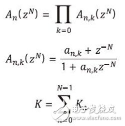

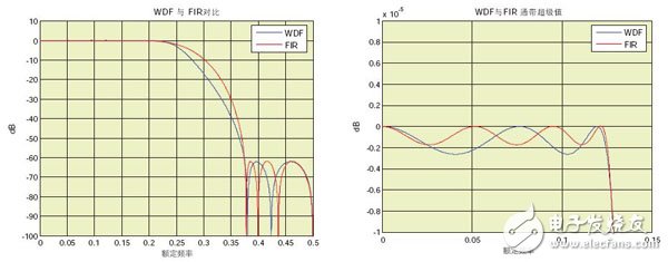
The method of generating coefficients for any order elliptic filter using a two-branch structure has been fully described in the monographs of RA Valenzuela and AG ConstanTInides [5]. Figure 5 shows a fifth-order (two coefficients a0=0.1380, a1=0.5847) WDF filter with a normalized passband of 0.125 compared to a 22-tap FIR filter designed using the Parks-McLaren algorithm. It can meet the same passband ripple and stopband attenuation specifications. The results show that the filter order usually drops to 1/4 of the original, and compared to the 11 multipliers used in FIR (considering the symmetry factor), WDF requires only two multipliers. 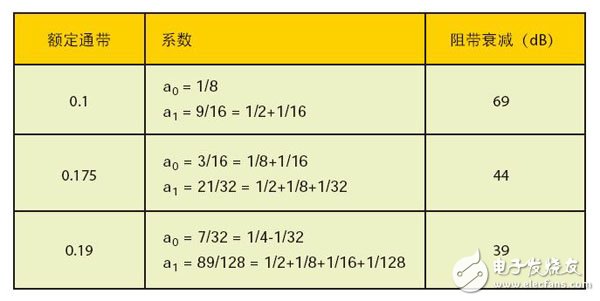
1. Xilinx White Paper WP330, "Infinite Impulse Response Filter Structure in Xilinx FPGAs", August 2009;
2. Author: PP Vaidyanathan, "multi-rate systems and filter banks", PrenTIce-Hall Press, New York, Englewood Cliffs, 1993 years;
3. Xilinx 7 Series DSP48E1 Slice User Guide, version 1.5, April 3, 2013;
4. Analysis: Artur Krukowski, Richard Morling, Izzet Kale, "N-path structure multi-phase quantization effects IIR", IEEE Transactions on measuring instruments, vol. 51 No. 6, December 2002;
5. OF: RA Valenzuela and AG ConstanTInides, "high efficiency Interpolation decimation digital signal processing schemes", Part G, No. 6 130 electronic circuits and systems, IEEE Conference Record, 1983.