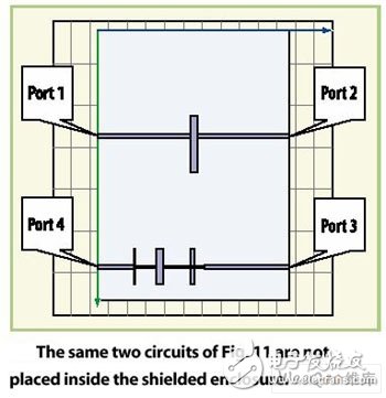
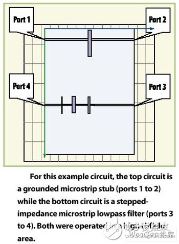
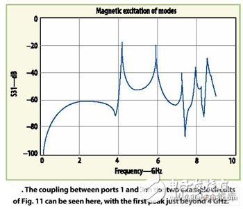
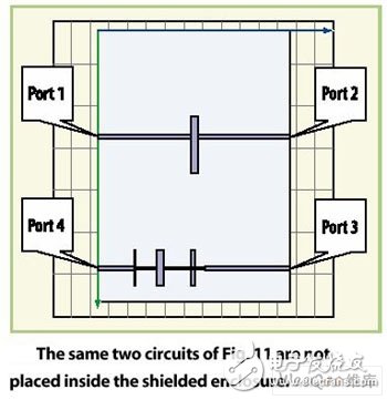
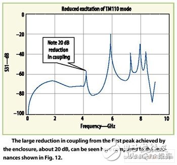
Shielding shells are often used to protect microwave printed circuit boards (PCBs). The shield case also protects the electrical performance of the circuit while protecting the PCB from the environment. If you understand the effects of shielded enclosures and how to predict these effects, you can improve the accuracy of most modern computer-aided engineering (CAE) simulation tools. This series of articles is divided into two parts. The accuracy of the shielding shell can be minimized by accurately predicting the frequency, position, and the intrinsic characteristics of the shielded shell induced resonance mode. The technique is summarized in the first part. One of the keys to avoiding unwanted resonance modes involves understanding the knowledge of the maximum electric field (E) and magnetic field (H), as well as the corresponding resonant frequencies. Careful placement and routing of the PCB circuitry can greatly reduce the effects of the resonant mode. To demonstrate this method, two filters are placed near the shield, and the first filter (A filter) is placed at the center of the shield, resulting in an E-field hot zone and at 4.1, 7.2, and 8.3 GHz. The TM110, TM210, and TM310 modes with expected field excitation at the frequency. Instead, a second filter (B filter) is placed towards the bottom of the shield cavity. In this region, the field strength is very small and the resonance effect is expected to be less than the effect of the first filter. Simulations with Ansoft HFSS Electromagnetic (EM) software also predicted that the placement resonance effect of the B filter was much smaller (see Figure 1). Another example gives the effect of an undesired coupling of one circuit to another (Figure 2). The circuit connected to port 1 to port 2 includes a grounded microstrip stub, and the circuit connected to port 3 to port 4 is a step impedance microstrip low pass filter. For all five modes described in the table, both circuits are near the high H field. Therefore, we should be able to anticipate resonance effects at frequencies of 4.2, 5.9, 7.2, 8.0, and 8.3 GHz. The energy curve of port 1 appearing at port 3 is shown in Figure 3. Note: At the predicted resonant frequency, there are 5 transmissions with fairly high peaks. If the same circuit is moved into the shield case (see Figure 4), a single grounded stub is placed at the H field zero of the TM110 mode, and the excitation of this mode is expected to decrease (see Figure 4). The remaining peaks are still significant, because the H field zero position in TM110 mode is actually the high or even the largest H field* point inside the shield in the other mode. The above simple simulation is used to prove that the layout and routing of the RF circuit inside the shield affects the degree of excitation in the resonant mode. In addition, it can be seen from the above E-field and H-field graphs that if the high-order mode is excited, the entire shield becomes very hot, so there is considerable controversy about choosing a circuit to reduce the resonant mode excitation. Finally, it is not too much to emphasize that the effective layout of the circuit can only reduce the effects of resonance, but it does not completely eliminate these effects. The only way to eliminate these problematic resonances is to change the size of the shield, keep the resonant frequency away from any frequencies present in the design, or use an RF absorber to actually change the size of the shield. The information presented here is only a general summary for decomposing and solving the problem of shield cavity resonance that would plague RF design. The frequency of the resonant mode can be roughly estimated using the simple formula given here. The primary and secondary mode hot zones should be determined prior to design to avoid the deficiencies of stimulating undesired modes. The optimum shielding size should be determined to reduce the effects of shielding resonance. In addition, the information presented here should help engineers identify and eliminate the problem of shielding resonances in existing designs. It is also a tool to identify the placement of RF absorbers or metal support rods to eliminate resonance modes. Acetate Glasses,Acetate Sunglasses,Acetate Eyeglasses,Acetate Round Sunglasses Danyang Hengshi Optical Glasses Co., Ltd. , https://www.hengshi-optical.com