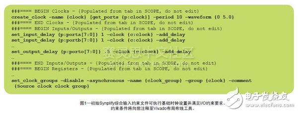
Existing tools and techniques can help you achieve your timing performance goals effectively. When your FPGA design fails to meet timing performance goals, the cause may not be obvious. The solution depends not only on the ability of the FPGA implementation tool to optimize the design to meet timing requirements, but also on the ability of the designer to specify the front target, diagnose and isolate downstream timing issues. Designers now have some tips to help you set the clock; set timing constraints correctly with tools like Synopsys Synplify Premier; then adjust the parameters to meet the performance goals of Xilinx FPGA designs. There are multiple points of attack, including: • Better design settings such as complete, accurate timing constraints and clock specifications; • Time-saving design techniques, such as careful RTL coding for better performance and the integration of design components that create the most performance issues, reducing the iterative runtime of subsequent adjustments to design timing. • Synthesize correlations and place and route timing to produce better timing quality (QoR) and timing closure. Now let's take a closer look at these techniques in three ways and test how to use them to achieve your timing goals. You need to make sure that you have fully and completely constrained your design and are not overly constrained. The biggest cost overhead comes from specifying correct and complete design constraints. These constraints enable communication between design intent and design performance goals and synthesis tools. Once integrated, these constraints and critical path information are automatically passed to the Vivado® Design Suite Place and Route (P&R) tool to further ensure timing requirements are met. Comprehensive tools can help you deal with the daunting task of setting up pre-integration constraints. Your task list is as follows: 1. Identify the clock 2. Identify and create clock groups and clock relationships 3. Constraint clock 4. Constraint design input and output 5. Define multi-cycle paths and wrong paths You need to make sure that your design is fully and completely constrained and not overly constrained. Excessive constraints will result in extended runtimes and the possibility to report critical paths of errors. Be sure to specify multiple cycles and error paths and set constraints on the derived clock (define_path_delay, define_false_path). Setting up the initial constraint file for the Vivado process is difficult because of the constraint setting work, so the synthesis software can provide an initial constraint template where the underlying constraints and syntax can be used as a starting point for this work. For example, in the Synplify synthesis software, run the TCL utility to create an initial FDC file for a particular design: TCL: create_fdc_template Figure 1 shows an example of a constraint file (.fdc) that will be generated by this process. In this example, you can see that key items such as the assertion clock, the clock group (the relationship between the clocks), and the input/output delay have been taken into account. Best Practices for Constraint Settings in the Vivado Design Suite Process When setting constraints in the Vivado Design Suite process, be sure to do the following: • Define the input port or all base clocks on the network connected to the input port. • Define the clock on the black box output pin. • Define the clock generated on the network. • Do not define a logic strobe clock. • Provide correct clock constraints: Do not over-constrain and ensure that unrelated (also known as asynchronous) clocks are placed in separate clock groups. • Define timing exceptions such as error paths and multi-cycle paths. Tip: In the Vivado Design Suite, the clock constraint should be as close as possible to the source clock, not the BUFG in the Xilinx ISE® Design Suite process. Make sure your constraints are correct We recommend four constraint verification techniques during the design setup phase. To give you an idea of ​​the type of constraint checking you should do, let's take a look at the checks performed by Synplify. First, run a "grammar check"—that is, quickly perform constraint checking, including its embedded "get_XX" and "all_XX" commands to discover and clean up any constraint syntax errors. Errors are displayed in the log file and can be hyperlinked to the error manual to explain the error and suggest changes. Use the Tcl command check_fdc_query. Second, run a "comprehensive check" to detect hardware-related errors, such as incorrectly written triggers. These errors are reported in a separate log file. Third, run the basic "quick synthesis" to check clock setup issues, including declaring, deriving, and inferring clocks. Fast synthesis support performs clock setup checks as it generates clock reports and timing reports, which clarifies clock setup issues. Some synthesis tools support running synthesis in "fast" mode, which disables some comprehensive optimizations in order to achieve shorter runtimes. In the Synplify Premier synthesis software, you can do this with the following commands: set_opTIon –fast_synthesis 1 The synthesis compiler will create a comprehensive report clock summary that you can use to identify, define, and constrain the clock. Fourth, run a comprehensive "constraint check". This check looks for constraint settings for clock relationships, unconstrained start/end points, unlocked I/O, and unconstrained I/O. A comprehensive constraint check will also find the correct application constraints and instance names. For example, it flags timing constraints that apply to non-existent or invalid parameters and objects. The tool then generates detailed interpretative reports for unapplied and unrecognized instances in order to correct the constraint file. The Synplify synthesis tool will automatically run these checks during the integrated pre-mapping phase, or you can run constraint checks using the following TCL commands at the start of synthesis: TCL: project -run constraint_check Box Header Connector,High Temperature Resistant Box Header Connector,Gold-Plated Box Header Connector,Plastic Box Header Connector Shenzhen Jinyicheng Electronci Technology Co.,Ltd. , https://www.jycconnector.com
