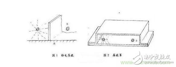
Modern radars require higher and higher signal spectrum quality and require radars to work reliably in harsh electromagnetic interference environments. This places higher requirements on the anti-electromagnetic interference and electromagnetic compatibility of radar circuit systems. Due to the spurious output of the radar signal, in addition to the signal conversion and other processes, it is also related to the interference outside the system, the interference between the circuits, the structural design of the circuit system, the process design, and the signal transmission and matching. The circuit system compatible with the requirements, in addition to a reasonable plan and correct design, must also pay attention to the following points. a. Take effective measures such as grounding of the circuit and removing noise between circuits to suppress all unrelated signals. b. Assembly design, circuit layout and arrangement must be correct and reasonable. c. Advanced process design should be adopted. d. Strengthen the shielding isolation between the unit circuit and the cable and the circuit system. When high-quality unit electronic circuits are used to compose a circuit system and perform certain functions, in addition to the correctness of the system scheme, electromagnetic compatibility design is also very important. Especially for high-stability signal systems and some complex circuit systems in modern radars and circuit systems operating in harsh electromagnetic environments, electromagnetic compatibility design is even more important. The following will analyze in detail the electromagnetic compatibility issues of the circuit system, and propose relevant implementation measures and methods. There are three forms of interference in the power system: the first is the interference from the outside of the system, such as the interference signals from the AC grid and interference from the magnetic field; the second is the interference signal generated by the system itself, such as the rectification filter. After the ripple interference, SCR voltage surge generated by the sharp pulse, high-frequency pulse caused by switching power supply, high-frequency power leakage and noise generated by the regulator, etc.; the third is the system connection line field interference signal . To suppress or attenuate these interference signals must be careful electromagnetic compatibility design of the power system. a. Add shielding and isolation measures to the power transformer. Each power transformer should be electrostatically screened between primary and secondary to isolate the interference from the primary grid string. Important power supplies should also be magnetically shielded across the entire transformer to cover high-magnetic materials, to suppress the transformer magnetic field and external magnetic field interference. These electrostatic and magnetic shields should be reliably grounded. b. The power transformer should be as far away as possible from the electronic circuit in order to minimize the interference of the power supply frequency and the interference of the magnetic field of the AC power supply. c. In the circuit system, if there are analog circuits and digital circuits at the same time, the analog circuits and digital circuits must be powered separately. Prevents transient processes with fast rise times in digital circuits from affecting analog circuits through power supplies. d. Reasonably assemble the circuit, correctly ground, correct wiring and laying cables. The use of appropriate magnetic shielding materials and electromagnetic shielding materials must also take into account the size, weight, and cost. There are two main aspects of interference in signal transmission. The first is that when a signal passes through a transmission line, an electromagnetic field is generated around it. These electromagnetic fields induce currents in the surrounding conductors to form interference signals. Second, signals are generally reflected during transmission, and the reflection signals are transmitted in series to interfere with other circuits. signal. To overcome the interference caused by transmission, the following measures can generally be taken. a. Strengthen the electromagnetic shielding. For different frequencies, different types of unit circuits can be combined and shielded to reduce mutual influence. b. Strengthen the matching and isolation of transmission signals so that the input and output of the signal have matching networks, and the isolation level is appropriately increased to reduce reflection interference. c. Suppress any undesired signal. Even if the signal falls outside the frequency band of the circuit, it should take measures to suppress it. Because there are non-linearities in common amplifiers, frequency multipliers, mixers, and frequency dividers, it is possible to transform out-of-band signals into the effective frequency range of the circuit. Therefore, if necessary, various filters should be added to suppress unwanted signals. d. Reasonable wiring and reasonable arrangement of circuits. The transmission lines on the printed board may become either transmitting antennas or receiving antennas. Therefore, they must be arranged rationally and their length should be shortened as much as possible to reduce their mutual interference. As the ground of the circuit system, the primary task is to have good contact and minimize grounding inductance and grounding resistance. Make the ground current less common and reduce mutual induction. In the circuit system, the analog signal ground, the digital signal ground and the noise ground should generally be separated, and some systems must be separately shielded. Analog circuits are used for analog circuits and their power supplies; digital signals are used for digital circuits and their feed power supplies; noise is used for electrostatic shielding and transformer shielding of AC power transformers, shielding and transmitters for AC power supply lines, and the like. These ground lines should not be confused in the circuit system, so that they are connected to the earth at a single point outside the system. Electromagnetic compatibility cannot be seen only as a matter of the circuit designer, but must also be coordinated by the process and structural personnel in order to accomplish a reasonable design. Because whether it is the setting of the grounding wire, the arrangement of the cable, or the shielding design of the electronic combination, the arrangement of the electronic combination and the placement of the transformer, and the selection of various materials are all problems of the electronic structure. The processing of shields, the fabrication of printed boards, and the assembly of circuits will directly affect the shielding, radiation and conduction effects. This is a technical issue. The following issues should be taken into account when designing. a. Reasonably divide and combine the unit electronic circuits so that they are combined into different functional block circuits according to their functions. Especially for the periodic pulse signal circuit, it is best to start and end within the same functional block, that is, in the same shielding box. b. The digital circuit and the analog circuit must be assembled separately, and the connection between them should be isolated. If necessary, they can be completely isolated by optocoupler devices. c. Cables that transmit high-stability signals, if necessary, add shielding jackets to the cables, or use semi-rigid cables and rigid cables. d, the arrangement of circuits and components should be reasonable, do not make the signal back, minimize the input and output coupling and various situations. e. Try to use the plane mounting circuit and do not ground it in a large area. The radiation resistance of the electromagnetic field is better than the three-dimensional circuit, which can greatly reduce the field radiation. f. Pay special attention to noise circuits, noise components, and their ground lines, such as relays, power transformers, high-power high-current devices, and high-voltage pulse circuits. g. Do not install high-power, high-current components on the shields to prevent their return currents from passing through the shields to create unwanted coupling disturbances. Shield design In electromagnetic compatibility design, shield design is a very important aspect. Shielding is an important means of suppressing all unrelated signals and can generally be divided into three types: electrostatic shielding, magnetic shielding, and electromagnetic shielding. 1 electrostatic shielding Any two charged objects in the space can generate an electrostatic field, and the change of one of the voltages in the space will inevitably cause the other to change, creating an electrostatic coupling. The mechanism of electrostatic coupling is caused by the presence of capacitance between circuits. The best way to overcome static electricity is to use a metal plate as an electrostatic shield. The two sources of interference are isolated by metal plates, or all the components on the circuit are mounted on one side of the metal plate. Like the surface mount circuit, good electrostatic shielding can be obtained. The specific shielding method, especially the shielding against the interaction of stray capacitance, should be fully considered at the initial stage of design. Shielding method: Put a metal plate in the middle of the two shielded circuits, and make the metal plates electrically connected to the ground, as shown in Figure 1. In this way, the power lines emitted from one point are all shielded by the shield plate, which acts as an electrostatic shield. A shield can also be made, as shown in FIG. 2 , and a good shielding effect can also be obtained. As can be seen from Fig. 2, the power line at point A does not reach point B, so it can also function as a good electrostatic shield. Increasing the distance between A and B to reduce the stray capacitance can also reduce the combinatorial effect of capacitance. However, this method is limited by the volume and generally cannot be used. Special attention should be paid to the contact between the electrostatic shield and the ground must be good, if the contact is not good, the potential difference between the shield and the ground will affect the shielding effect. Therefore, it is required that the shielding box should be treated with anti-corrosion. The screws and rivets used should not be too thin. Try to make the electrical contact as good as possible, reduce the grounding resistance, and reduce the grounding inductance. 2 magnetic shielding When the current flows in the wire and flows through the inductor and the transformer, a magnetic field is generated around the inductor and the magnetic field is transmitted through mutual inductance in the circuit. The magnetic force generated by the current induces a voltage in other circuits through mutual inductance. Especially in the following low frequency conditions of 3KH: the main interference effect is caused by the magnetic field, but solving magnetic shielding is often both expensive and difficult. In radars, magnetic shielding is mainly aimed at power transformers and high voltage modulators. Generally low ripple power transformers are often screened with permalloy, otherwise they do not achieve good results. 3 electromagnetic shielding Any type of AC circuit will produce alternating electric and magnetic fields. Electromagnetic shielding is related to the nature of the electromagnetic field, the frequency of change, and the distance between the radiation source and the sensor. In radar electronic circuit systems, the operating frequency is generally high. Above IKHz, aluminum can generally be used as an electromagnetic shielding material. The aluminum shield box made by cutting process can shield signal isolation up to 100dB above 300MHz. When the frequency is below kHz, mainly shielding the magnetic field, high permeability material should be selected. In the electronic circuit system, in order to facilitate the internal wiring and taking out the placement circuit, a cover plate is added to the shielding assembly box, and in order to ventilate, dissipate heat, etc., a hole is punched in the shielding plate, and a slit is opened, resulting in a break point in the shielding body. Cause signal leakage and interference, designers should seriously consider. Correctly arrange the components so that the slits and holes do not cut off the induced current. If necessary, the holes can be switched to cut-off waveguides to further weaken the hole radiation. Shielding assembly design In addition to shielding design, assembly technology is also very important, especially for the assembly of radio frequency systems, should be carefully designed. Should generally pay attention to the following points. a. The shielding design of the internal circuit should prevent the leakage of the RF energy of the electronic circuit itself and also prevent the external electromagnetic energy from affecting it. b. Take measures to prevent unnecessary feedback and coupling between the circuit level and the level. c. Filter the power supply to the pan to suppress the attenuation. The RF signal is transmitted between the electronic combination and the electronic combination and combination. d. The smaller the RF grounding resistance, the better. Of course, the requirements of volume, weight, and cost must also be taken into account. When the circuit between the parasitic field attenuation requirements are higher, the assembly box structure is better, it can be made into a single isolation chamber form, it can also be designed into a number of isolation rooms form, that is, a shielding box, divided into several isolation Room, this assembly box has good isolation of both electrostatic and electromagnetic fields. The material used to make the assembly box is preferably aluminum. It is cheap and light, and it is generally good for radar circuit systems. When assembling these shields, long leaks are often encountered, and the necessary measures should be taken to make the long seams have many contact points. Available screws, additional elastic sheets and lining conductive pads and other measures. But this must pay attention to anti-corrosion, in particular, electrochemical anti-corrosion, otherwise it can not maintain satisfactory results for a long time. It should also consider the interference of radio frequency wire, reasonably select the amplitude of the transmission signal, and correctly arrange the system cable direction and pulse signal line. AC signal lines should not be tied together, especially for large pulse signals, and should be strictly distinguished from high-purity signals in transmission. In short, shielded design is a more complex design. It not only requires knowledge of mechanical design, but also must be familiar with the knowledge of the various corpses involved.
ZGAR PCC
ZGAR electronic cigarette uses high-tech R&D, food grade disposable pod device and high-quality raw material. All package designs are Original IP. Our designer team is from Hong Kong. We have very high requirements for product quality, flavors taste and packaging design. The E-liquid is imported, materials are food grade, and assembly plant is medical-grade dust-free workshops.
From production to packaging, the whole system of tracking, efficient and orderly process, achieving daily efficient output. We pay attention to the details of each process control. The first class dust-free production workshop has passed the GMP food and drug production standard certification, ensuring quality and safety. We choose the products with a traceability system, which can not only effectively track and trace all kinds of data, but also ensure good product quality.
We offer best price, high quality Vape Device, E-Cigarette Vape Pen, Disposable Device Vape,Vape Pen Atomizer, Electronic cigarette to all over the world.
Much Better Vaping Experience!
E-Cigarette Vape Pen,Disposable Device Vape,Vape Pen Atomizer,Latest Disposable E-Cigarette OEM vape pen,OEM electronic cigarette ZGAR INTERNATIONAL(HK)CO., LIMITED , https://www.sze-cigarette.com