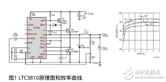
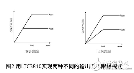
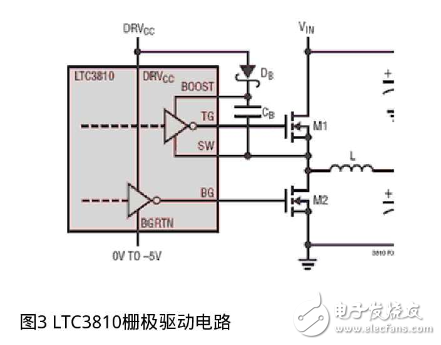
There are harsh and unmanageable environments in industrial, automotive, aerospace and data communication systems, so robust electronic systems are needed. In data communication systems, the input voltage can vary from 47V to 53V, and the transient voltage can reach 80V. In automotive systems, the DC battery voltage may be 12V, 24V, or 42V, and load dump conditions can cause transient voltages of up to 100V. In aerospace and industrial systems with a nominal 28V, the transient voltage can reach 55V. In these applications, some designs that require complete isolation use a power transformer and some methods to detect the feedback voltage, or provide voltage feedback through an optocoupler or transformer to detect the feedback voltage. But this high voltage is often a surge that lasts only a few milliseconds, so the DC/DC converter can be non-isolated. Then, it is clear that there is a need for a non-isolated DC/DC converter that can operate normally at such high peak voltages without damage without downtime, failure, or lockout. There is also a need for a non-isolated intermediate bus converter that converts a 48V backplane voltage to 12V or less. Data communication systems typically have a 47V to 53V distributed bus power supply that is isolated from the AC power source. Most intermediate bus converters are also isolated, thus resulting in double isolation when used in data communication applications, which adds complexity, may reduce the overall efficiency of the system, and may increase costs. Engineers are also often faced with the challenge of working with high input voltages in the 48V range while being able to produce outputs as low as 1.8V. High input voltage rails above 12V often require an intermediate voltage regulator stage, which reduces overall efficiency and increases overall cost. However, synchronous buck controllers with a minimum turn-on time of only 100ns can be used in high step-down ratio applications to generate low voltage directly from high input rails. Fortunately, Linear Technology's LTC3810 current-mode synchronous DC/DC switching regulator controller can directly step down the input voltage up to 100V, making it ideal for harsh input voltage environments and non-isolated intermediate bus converters. The ability to step down directly to high input voltages allows for a simple single inductor topology for a compact, high performance power supply without the need for low-side drive isolation topologies that require bulky, expensive transformers. The LTC3810 uses a synchronous, constant on-time, valley current mode control architecture to drive two external N-channel MOSFETs. Large bandwidth error amplifiers enable fast voltage and load transient response. A powerful 1Ω gate driver minimizes switching losses (switching losses are often the dominant loss component in high voltage power supplies), even when multiple MOSFETs are used in high current applications. Figure 1 shows the LTC3810-based non-isolated DC/DC converter schematic and efficiency curve with an input voltage range of 15V to 100V, producing 12V and up to 6A. The LTC3810 has an internal linear regulator controller that uses a single external MOSFET to generate a 10V bias supply voltage from the input voltage. This MOSFET is shown in Figure 1 with reference number M3. This allows the user to use the controller without a separate bias voltage and reduce internal heat by transferring the LDO channel components out of the controller. For continuous operation, the minimum power rating of the M3 can be calculated using the following formula: Power consumption in M3 = VIN - 10V*IBIAS The bias current (IBIAS) is approximately 20mA, depending on the gate drive power required to drive M1 and M2. 10V is the output voltage that powers the LTC3810, VIN is the average input voltage, and the peak voltage averages to the total steady-state voltage. If the output voltage is above 6.7V but below 15V, the internal LDO fed from the output voltage through the EXTVcc pin can be used to power the LTC3810 for maximum efficiency and will turn off the MOSFET M3 after the output voltage reaches 6.7V. . Since the M3 only consumes power during a short start-up, careful selection of the size specification makes it possible to use a relatively small MOSFET (eg SOT-23). The LTC3810 is a valley current mode controller. During normal operation, the top MOSFET is turned on at regular intervals, and the time interval is determined by a single timer. When the top MOSFET is turned off, the bottom MOSFET turns on until the current comparator transitions, then restarts the one-shot timer and starts the next cycle. The inductor current is determined by sensing the voltage across the SENSE pin with a sense resistor or the on-resistance of the bottom MOSFET. The voltage setting on the ITH pin corresponds to the comparator threshold of the inductor valley current. The 25MHz fast error amplifier regulates the output voltage by comparing the feedback signal to the internal 0.8V reference. If the load current increases, there is a voltage drop relative to the reference feedback voltage. The ITH voltage then rises until the inductor average current again matches the load current. In a typical LTC3810 circuit (see Figure 1), the feedback loop consists of a routing modulator, an output filter, and a feedback amplifier with a compensation network. All of these components affect the performance of the loop and must be taken into account in loop compensation analysis. By shifting the inductor into the loop, current mode control eliminates the effects of the inductor, simplifying loop analysis to a first-order system. If you use voltage mode to control the regulator, figuring out how to design a compensation network to maintain stability over a wide range of input and output voltages can be a daunting task. Because the LTC3810 is a current mode control device, the task of designing a feedback loop is much easier and can be designed with a Class 2 error amplifier. In addition, Linear Technology offers design tools in the form of Excel spreadsheets that greatly simplify the selection of loop compensation components. Linear Technology also offers the SwitcherCAD III simulation model, making it possible to properly size the entire circuit through simulation before making the board. The LTC3810 (with programmable current sense threshold) provides short-circuit and overload protection with or without current sense resistors. Using a sense resistor in series with the bottom MOSFET provides a precisely defined current limit, but increases cost and reduces efficiency. The bottom MOSFET can also be used as a current sense component to remove the sense resistor. Tracking provides a predictable way to increase or decrease the output voltage as other voltage rails in the system change. Tracking keeps the feedback voltage at the lower end of the internal reference or TRACK pin voltage. The LTC3810 goes one step further by combining the trace and soft-start functions (TK/SS pins) on a single pin and determining the switch mode of operation based on the state of this TK/SS pin. Figure 2 shows consistent and proportional tracking, both of which can be configured with the LTC3810. The LTC3810 includes a very low impedance gate driver that provides ampere current to quickly convert large MOSFET gates. This minimizes conversion losses and allows parallel MOSFETs for applications with higher output currents. A floating high side driver (up to 100V) drives the top MOSFET, while a low side driver drives the bottom MOSFET (shown in Figure 3). The LTC3810 provides power supply designers with a way to protect equipment from high input voltage damage up to 100V, which is often the case in harsh applications such as aerospace, industrial control systems, automotive, telecommunications, and datacom applications. It is important to minimize the amount of internal IC heat that can be caused by an on-board LDO for internal bias voltage. The LTC3810 provides the drive voltage to the external MOSFET and controls the MOSFET to generate this bias voltage, allowing the IC to operate at lower temperatures over a wide input voltage range. If a separate bias voltage is available, it can also be used directly to power the LTC3810, which removes the external MOSFET. The LTC3810 features a current mode control, a powerful built-in MOSFET driver, the ability to operate without sense resistors, synchronize to an external clock, and control the output voltage during power-up and power-down, making the LTC3810 a harsh high peak. An excellent choice for DC/DC converter applications in voltage environments. 800 Puffs Vape,Electronic Smoke,Puff Bar Electronic Cigarette,Pure Smoke Electronic Cigarette Guangzhou Yunge Tianhong Electronic Technology Co., Ltd , https://www.e-cigaretteyfactory.com