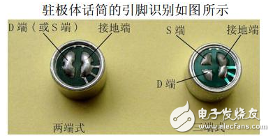
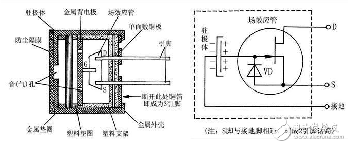
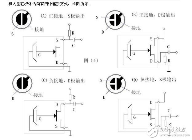
The working principle of the electret microphone: When the electret diaphragm encounters the acoustic vibration, it will cause a change in the distance from the metal plate, that is, the capacitance between the electret diaphragm and the metal plate follows the sound wave. The change, in turn, causes a change in the electric field inherent to both ends of the capacitor (U = Q / C), resulting in an alternating voltage that varies with the change in sound waves. Since the capacitance of the electret film and the metal plate is relatively small (generally tens of wave method), its output impedance value (XC=1/2πfC) is very high, about tens More than megaohms. Such a high impedance cannot be directly matched to the input of a general audio amplifier, so a junction field effect transistor is connected to the microphone for impedance transformation. The voltage across the "capacitor" is taken out by a field effect transistor with a very high input impedance, and amplified at the same time, and an output voltage signal corresponding to the sound wave is obtained. The FET inside the electret microphone is a low-noise dedicated tube. The gate V and the source S are combined with a diode VD. See Figure 1(b), which mainly functions as an "anti-blocking". Since the FET must operate under the appropriate applied DC voltage, the electret microphone is an active device, that is, the electret microphone must be applied with a suitable DC bias voltage to ensure that it works properly. It is different from the general dynamic coil type, piezoelectric ceramic microphone. Shape and type: The shape of the common electret microphone is divided into two types: the built-in type and the external type. Machine-mounted electret microphones are suitable for installation in a variety of electronic devices. The common machine-mounted electret microphones are mostly cylindrical in shape, and their diameters are φ6mm, φ9.7mm, φ10mm, φ10.5mm, φ11.5mm, φ12mm, φ13mm, and the pin electrodes are divided into two ends. There are two types of three-terminal type, the lead type of the lead-in type with the soft-shielded wire and the lead-type type without the lead wire which can be directly soldered on the circuit board. If classified by volume, there are two types: normal type and miniature type. Working voltage: Uds1.5~12V, commonly used 1.5V, 3V, 4.5V Working current: between Ids 0.1~1mA Output impedance: generally less than 2K (ohms) Sensitivity: unit: volt / Pa, domestically divided into 4 files, red dot (highest sensitivity) yellow dot, blue dot, white point (lowest sensitivity) Frequency response: generally flat Directivity: omnidirectional Equivalent noise level: less than 35 decibels The method for detecting an electret condenser microphone is to first check the pin for disconnection and then detect the electret condenser microphone. The electret microphone is small in size, simple in structure, good in electroacoustic performance, low in price, and widely used. The interior of the electret microphone consists of an acoustic-electrical conversion system and a FET. There are two ways to connect its circuit: source output and drain output. The source output has three lead lines, the drain D is connected to the positive pole of the power supply, the source S is grounded via a resistor, and then output via a capacitor; the drain output has two lead lines, and the drain D is connected to the positive pole of the power supply via a resistor, and then A capacitor is used for signal output, and source S is directly grounded. Therefore, the polarity of the electret microphone must be determined first. A diode is connected between the gate and the source of the FET, so that the forward and reverse resistance characteristics of the diode can be used to distinguish the drain D and the source S of the electret microphone. Dial the multimeter to R&TImes; 1kΩ, the black pen is connected to either pole, and the red pen is connected to the other pole. Then adjust the two test leads and compare the two measurement results. When the resistance is small, the black meter is connected to the source, and the red meter is connected to the drain. Polarity detection of electret microphone: Dial the multimeter to “R&TImes;100†or “R&TImes;1k†electric block, black pen to any one pole, red pen to another pole, read the resistance value; After that, the resistance value is read again, and the two measurement results are compared. In the case where the resistance value is small, the black test pen is connected to the source S, and the red test pen is connected to the drain D. At the same time, the resistance is large and small, which also shows that the quality of the electret microphone is good. If the measured resistance value is ∞, or equal to 0Ω, or the resistance value is close, the microphone is damaged or the quality is not good. Turn the multimeter to “R&TImes;100†or “R×1k†electric block. According to the figure (a), the black test pen (the internal battery of the multimeter) is connected to the drain D of the two-terminal electret microphone. The test pen is connected to the ground (or the red pen is connected to the source S, and the black pen is connected to the ground). At this time, the pointer of the multimeter is indicated on a certain scale, and then the mouth is pressed against the sound hole of the microphone, and the pointer of the multimeter should be larger. swing. The larger the range of the pointer swing, the higher the sensitivity of the microphone under test. If there is no response or the reaction is not obvious, the microphone under test is damaged or the performance is degraded. For the three-terminal electret microphone, as shown in Figure (b), the black test pen is still connected to the drain D of the microphone under test, and the red test pen is simultaneously connected to the source S and the ground (metal case), and then blows in the same way. Gas detection is enough. Turn the multimeter to R×100, and connect the two pens to the two electrodes of the microphone (be careful not to connect to the grounding pole of the microphone). After the multimeter displays a certain reading, gently blew the air with the nozzle (the blowing speed is slow) Uniform), observe the swing amplitude of the hands while blowing air. The greater the amplitude of the needle swing at the moment of blowing, the higher the sensitivity of the microphone and the better the effect of sending the recording. If the swing amplitude is not large (nit-motion) or does not swing at all, it indicates that the performance of this microphone is poor and should not be applied. For the three-pin electret condenser microphone, the detection method is the same as above, except that the black bar is connected to the output pin 2 pin, and the red bar is connected to the pin 3 pin. We make OBD connector with terminal by ourselves,
soldering type and crimping type are both available. Also 12V and 24V type. OBD1, OB2, J1939, J1708, J1962, etc. Also molded by different
type, straight type or right-angle type. The OBD connector cables used
for Audi, Honda, Toyota, BWM, etc. We have wide range of materials
source , also we can support customers to make a customized one to
replace the original ones. Vehicle Diagnostic Cables,Diagnostic OBD Cable,OBD2 Splitter Y Cables,OBD2 Diagnostic Adapters,OBD Heavy Vehicle Cables ETOP WIREHARNESS LIMITED , https://www.oemmoldedcables.com


Homemade 9014 microphone circuit diagram (electret microphone / high sensitivity microphone)
Homemade 9014 microphone circuit diagram design