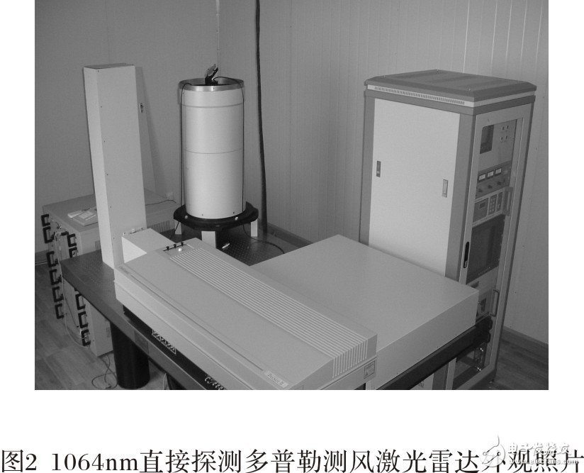
Wind is an important parameter for studying atmospheric dynamics and climate change. Using wind data, we can obtain changes in the atmosphere and anticipate changes, and promote human understanding of energy, water, aerosols, chemistry and other air material circles. Meteorological analysis and ability to predict global climate change. Current wind farm data are mainly derived from radiosonde wind gauges, ground stations, ocean buoys, observation vessels, aircraft, and satellites, which have significant limitations in coverage and frequency of observation. Direct global 3D wind field measurements have been mentioned on the agenda, and the World Meteorological Organization has put forward an urgent need for high-resolution atmospheric wind field data worldwide. So far, Doppler wind lidar is the only one that can obtain direct 3D wind. Field profile tools with the potential to provide the data needed globally [1]. Lidar is a powerful tool for detecting the atmosphere. With the development of laser technology, optical machining technology, signal detection, data acquisition and control technology, the development of laser radar technology is changing with each passing day. Doppler wind lidar has the advantages of practicability, high resolution and three-dimensional observation, which is unmatched by other detection methods [2, 3, 4]. The newly developed 1064 nm direct detection Doppler wind lidar uses dual edge technology to detect the tropospheric three-dimensional wind field [5]. This paper introduces the overall structure of the laser radar and the functions of its various parts, and analyzes and discusses the preliminary results of detecting the tropospheric wind field. 1064 nm direct detection Doppler wind lidar is composed of laser emitting unit, two-dimensional scanning unit, echo signal receiving unit, signal detection and data acquisition unit and control unit. The structure diagram and appearance photo are respectively See Figure 1 and Figure 2. The main technical parameters are shown in Table 1. The laser emitting unit, the echo signal receiving unit, the signal detecting and data collecting unit are placed on the optical platform to ensure optical stability. The center wavelength of the Nd:YAG laser is 1064 nm. At this wavelength, it can have a large laser output power, and the backscattering cross section of the aerosol is relatively large. The pulse repetition frequency is 50 Hz, which can save the detection time and capture the change of wind speed in a short time, which is beneficial to improve the accuracy of wind speed detection. At the same time, the laser laser is injected inside the laser to ensure the frequency of the laser is stable. The two-dimensional scanning unit is placed on the roof of the experimental room and receives the top of the telescope. A large-diameter optical periscope structure consisting of two planar mirrors, a horizontal rotating mechanism, and a vertical rotating mechanism coated with a 1064 nm wavelength all-reverse dielectric film. It can scan in all directions by software control or manual adjustment. The horizontal direction can be rotated from 0o to 360o, and the vertical direction can be rotated from 0o to 180o. The four-beam method is used for conventional detection, and the horizontal orientation is detected in four directions of 0o, 90o, 180o and 270o, that is, four directions of east, south, west and north, and the working elevation angle is 45o. The receiving telescope is directly below the two-dimensional scanning unit, and the effective aperture is 300 mm, as shown in Figure 1. The main mirror is coated with a 1064 nm wavelength full-reverse dielectric film with a reflectivity of up to 99%. The atmospheric backscattered echo signal received by the telescope is coupled to the optical fiber, which is introduced into the collimator by the optical fiber and becomes parallel light. After passing through the narrowband filter of the background light, the 20% reflection and 80% transmission splitter is divided into two. Two parts. 20% of the reflected signal is used as energy detection, and is divided into two beams by a right-angle reflection prism, which are respectively received by the photon counting detector; 80% of the transmitted signal is detected as a signal, after passing through two channels of the double Fabry-Perot etalon, The rate is different, and two light signals of different intensities are obtained, which are divided into two beams by a right-angle reflecting prism and received by the corresponding photon counting detectors. The four photon counting detectors convert the optical signal into an electrical signal, input it into the photon counting card, and finally store and process the collected data by the main program in the industrial computer, and display the measured signal strength profile and wind speed in real time. And the wind. An industrial computer is installed in the control cabinet. The system operation control software of the 1064nm direct detection Doppler wind lidar installed in the cabinet is controlled by the RS232 serial port control laser, the two-position scanning unit and the dual Fabry-Perot etalon. Overall coordination. The control cabinet also has a controller CS100 with dual Fabry-Perot etalon, a controller for the two-position scanning unit, a door control device, and a power supply for the monitor and components used in the coaxial system for light. One of the key technologies for 1064nm direct detection of Doppler wind lidar is the use of high-resolution dual Fabry-Perot etalon, which forms two semi-circles of the same area and size by coating or deposition on a pair of substrates. The interferometer can separate the two channel spectral centers of the etalon according to the thickness of the coating to form an overlap of the transmittance response curves. Since they are fixed on a substrate, the relative positions of the center frequencies of the two channels of the dual Fabry-Pero etalon are the same as the temperature drift, ensuring that the spectral center spacing of the etalon is constant. The transmittance curve of the dual Fabry-Perot etalon is measured by the CS100 control subroutine of the system operation control software to obtain the corresponding curve of frequency and transmittance. Figure 3 is the transmission curve of the double Fabry-Perot etalon obtained from the 500-pulse cumulative average measurement at 19:04 on April 27, 2005. The spectrum of channel one (real dot) and channel two (virtual dot) The center interval is 228.2 MHz, and the half width is 205.0 MHz and 224.3 MHz respectively. The real curve and the dashed curve are the corresponding fitting curves of the two channels respectively, and the peak transmittances are 73.7% and 70.8%, respectively. The measurement results correspond to Table 1. The technical parameters are basically the same. The drift of the optical unit and the electronic device due to environmental factors, and the movement of the operator may cause the vibration of the receiver component to cause the cavity length drift of the dual Fabry-Perot etalon, and the drift of the frequency caused by the long working of the laser, both to the standard Measurements with transmission curves have an impact. In order to test the performance of the double Fabry-Perot etalon, from April 24, 2005 to May 15, 2005, 8 measurements were made. The transmittance response curve is shown in Figure 4. The real curve and the dashed curve correspond to channel one. And channel 2 transmittance response curve. It can be seen from the figure that although the time is 21 days apart, the coincidence of the transmission response curves of the 8 groups is very good, indicating that the stability of the system is very good.
Rectangular I/O Connectors
Antenk develop and specify high-performance I/O's throughout a wide variety of industries. These include SAS, SATA, PCIe, HSSG, FIBRE CHANNEL, INFINIBAND, IEC, CEA, IEEE, VESA, USB and many more.
I/O Connectors Application
Antenk can deliver standard and custom options of the following I/O connectors:
I/O Connectors General Specifications
ELECTRICAL CHARACTERISTICS
Rectangular Connector,Rectangular I Connectors,Rectangular O Connectors,Male Connector Rectangular,I/O Connectors,Input/Output Connectors ShenZhen Antenk Electronics Co,Ltd , https://www.antenkelec.com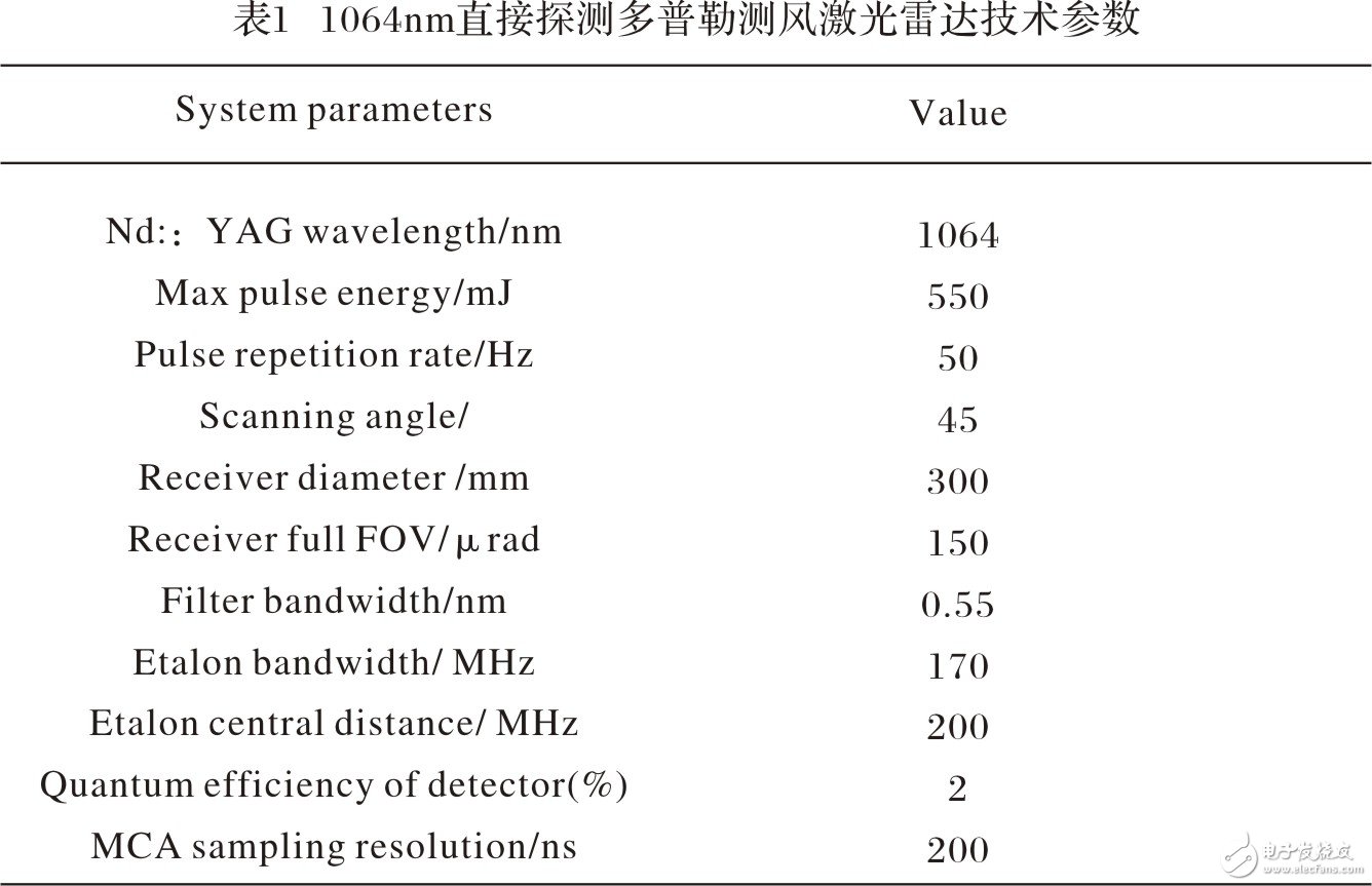
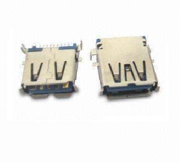
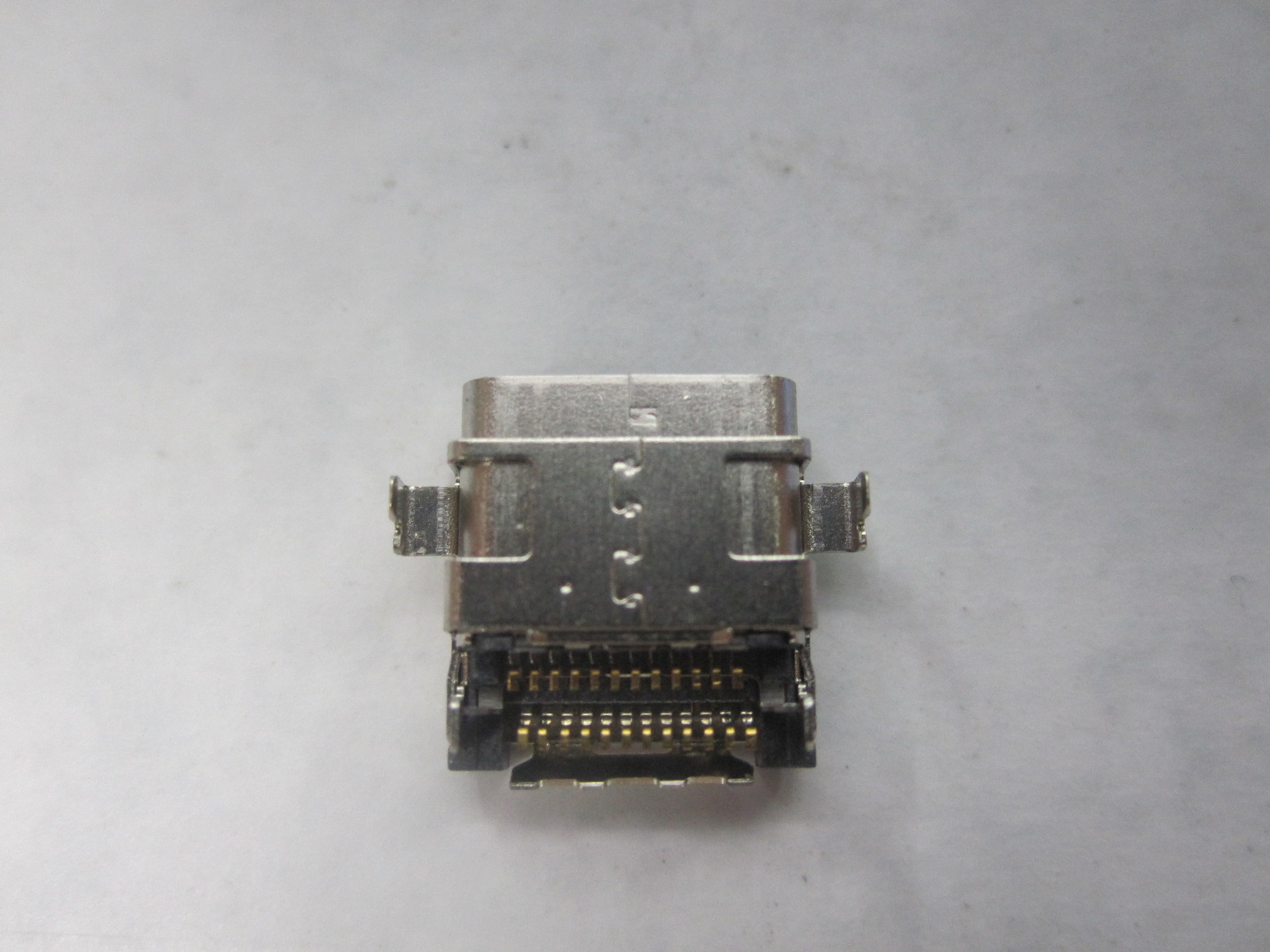
Antenk offers an expansive product line of I/O connectors including USB, HDMI, D-Sub, Modular Jacks, SFP, QSFP+, CXP, iPass+, iPass+ HD and more. In addition to standard I/O connectors and matching cable assemblies.Except a comprehensive range of standard Input/Output connector solutions for high-speed electronic data communication, Antenk engineers can design customized solutions. This extensive selection of I/O connectors and matching cable assemblies includes numerous next-generation solutions.All of our I/O connectors feature a variety of orientation options, as well as PCB and cable mount offerings.
Consumer / PC Products
Networking / Telecommunications Products
Mobile Products
Industrial Products
1394 Connector
Centronic Connector
D-Sub Connector
DVI Connector
Display Port Connector
HDMI Connector
Half Pitch SCSI Connectors
USB Connector
V.35 Connector
OBD Connector
Contact Current Rating:5Amperes.
Dielectric Withstanding.
Dielectric Withstanding Voltage:AC 1000Vr.m.s.
Insulation Resistance:500 Megohms Minimum at DC500V.
Contact Resistance:25 Milliohms Maximum.
Operating Temperature:-55℃~105℃.
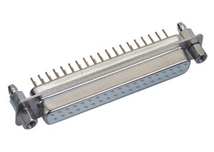
MATERIALS:
Contacts:Brass.
Insulator:PBT,UL94V-O Rated.
Shell:Cold Rolle Steel.
Metal Watertight Frame:PBT,UL94V-0.
O-Ring:Silicone.
NOTE:
Position:09PIN,15PIN,25PIN,37PIN.
Introduction to the overall structure and technical parameters of the self-made direct detection Doppler wind lidar
introduction