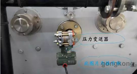
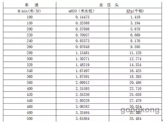
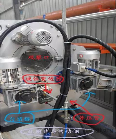
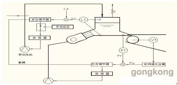
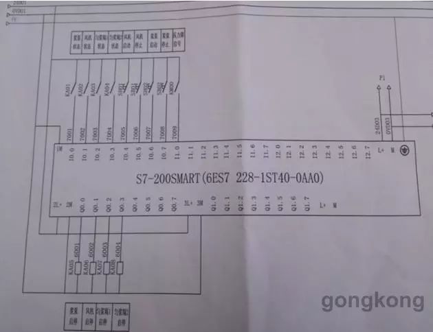
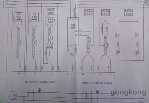
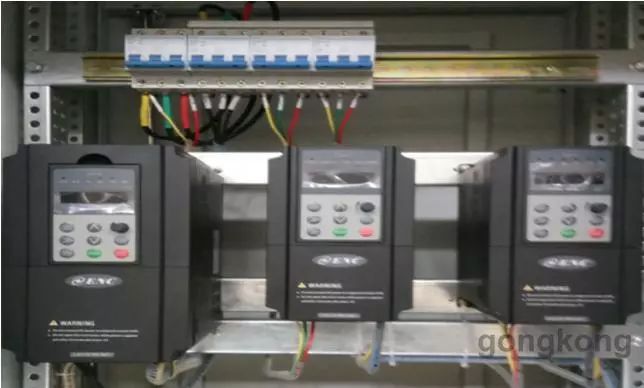
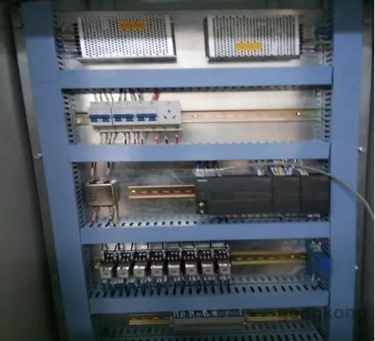
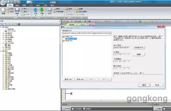
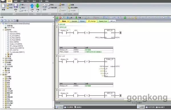
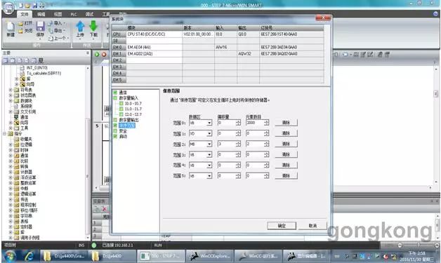
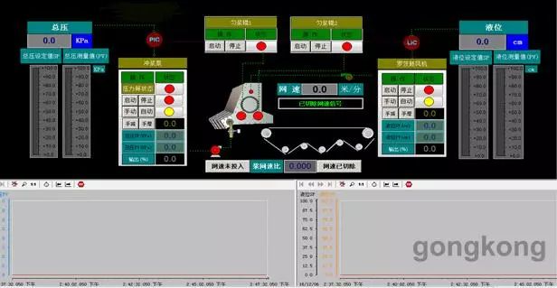
one. introduction The headbox (also called the headbox) is an important part of the paper machine. Its main function is to produce a stable flow of the Internet and ensure the uniformity of the paper. The uniformity of the paper formation depends on the degree of dispersion of the fibers in the headbox and the evenness of the headbox lip. For paper machines with a speed less than 200m/min, open headboxes are generally used, that is, self-priming headboxes. The total pressure is controlled by the pulp level, and on paper machines with a speed exceeding 200m/min, air cushions are generally used. In the headbox or (semi-)hydraulic headbox, the control parameters mainly include the total pressure, pulp level, and slurry speed ratio. The purpose of controlling the total pressure is to obtain uniform pulp flow from the headbox to the web. With the flow rate, the purpose of controlling the pulp level is to obtain an appropriate pulp basin to reduce lateral flow and concentration changes, generate and maintain controlled flow of water to limit fiber flocculation. This article takes an air-cushioned headbox as an example to introduce its system hardware and software design. two. On-site process requirements and equipment overview 1. Total Indenter Control Overview In an air-cushion headbox, P = P' + H, where P is the total head pressure, P' is the cushion pressure, and H is the pulp level. By changing P' to stabilize H, the total pressure head controls the spraying speed of the headbox. It is regulated by the speed of the sizing pump. The stability of the total head has a greater influence on the longitudinal sizing of the paper. The pressure control loop works at its best. 1) The total pressure head detection: pressure transmitter PT-101, detection pressure head, pressure transmitter measurement range of 0 ~ 40KPa (adjustable according to actual conditions), the output electrical signal is 4 ~ 20mA DC. Physical installation as shown 2) Total Indenter Setting: There are two setting methods for the total indenter set value Ps. One is to directly set the (predetermined value) in the host computer and send it to the SIEMENS PLC through the communication interface; the other is to put the network on the host computer. Speed ​​w and pulp speed ratio αs, the computer calculates the total pressure value according to the formula Ps=K×(αs×W)2, and sends it to SIEMENS PLC through the communication interface. 3) Total pressure head control: The computer gives the control signal (4~20mA DC) according to the set value of the total pressure head, the measured value and the coupling relationship between the total pressure head and the pulp position, after corresponding control processing. The speed of the sizing pump is controlled by the sizing pump inverter. If the actual value of the total ram is lower than the given value, the sizing pump speed is increased; otherwise, the sizing pump speed is reduced until the total ram reaches the set value. . The sizing pump can also be manually controlled, that is, the output of the inverter is placed in the “manual†position on the man-machine interface, and the speed of the sizing pump is directly controlled. 4) Control of pulp speed/speed ratio: The composition of the paper sheet in the vertical and horizontal directions is consistent with the pulp injection speed and speed on the lip of the headbox, and the total pressure of the headbox determines the pulp. The speed of shotcrete is α=J/W=60√2gP/V where P is the total head, W is the speed of the wire, and α is the speed ratio of pulp speed. In actual use, due to the lip opening, The shape of the headbox is different, and the set value α of α is not the same. Therefore, it needs to be determined according to the actual situation. For the equipment without the pulp speed ratio control, the comparison table is generally listed by manual calculation. The operator manually adjusts the total head setting according to different vehicle speeds. In this system, the total pressure can automatically follow the speed change (with speed input module), and through the keyboard input, you can easily change the value of αs to meet the requirements of the process; at the same time, under the conditions of different pulp speed ratios, The total pressure-speed comparison table is available for the operator to query. The total pressure parameter table is as follows The total head pressure comparison table: (αS=0. 5) Normal operation: When the system is running, the computer will automatically control the speed of the sizing pump to ensure that the actual value of the total ram changes within the allowable range around its given value. 2. Pulp position control In a double-homing roller air-cushion headbox, the pulp level control loop is an intermediate link in the total pressure control loop. During the total pressure adjustment process, the pulp level will be constantly fluctuating, which depends on the adjustment of the pulp level. The circuit is continuously adjusted to stabilize the liquid level at a certain height. 1) Detection of pulp level: The differential pressure type liquid level transmitter LT-102 is used to detect the pulp position. The flange part is installed on the outside of the bottom of the headbox. The low-pressure side is mounted on the outside of the upper part of the headbox through the guide pipe, and the height of the pulp level is measured based on its differential pressure. Such as 2) Pulp position setting: set between 0.2-0.4 meters according to actual requirements 3) Pulp position control: The computer gives the control signal (4~20mA DC) according to the setting value of the pulp position, the measured value and the coupling relationship between the slurry and the total pressure head after the corresponding control processing. The controller controls the amount of air blown by the Roots blower. If the pulp level is low, then reduce the air volume. On the contrary, if the pulp level is high, increase the air volume until the liquid level reaches the set value. The speed of the fan can also be set to the manual state on the man-machine interface, and the speed of the fan can be manually determined. This feature can be used when debugging. 4) Normal operation: The ideal pulp level adjustment should make the pulp level fluctuations in the allowable range not only ensure that the slurry surface and the bubbles in the slurry surface overflow all through the overflow tank, but also the influence of the pulp level adjustment on the total pressure head. Is the minimum. 3. Control diagram three. Electrical hardware design According to the technical agreement, the Siemens 200 SMART series PLC is used to control a Roots blower, a slurry pump and two homogenizer rollers. There are 4 motors in total. (The fans and the two homogenizer rollers are controlled by the ENC600. (Plug pump user-supplied) After the other equipment is turned on, feedback must be designed to meet the user's requirements. At the same time, the level transmitter and pressure transmitter in the headbox must be controlled. In addition, redundancy is reserved for the convenience of operation. Drawings are as follows four. PLC programming Some data in the program must have the power-off save function, you must set the following parameters V. Upper computer program design Design corresponding buttons, bar graphs, trend charts, etc. according to user requirements, as shown below VI. On-site commissioning There are three-phase power cables in this equipment, as well as signal lines, which must be laid separately for system stability in order to meet the control requirements. After power on, check whether the communication is normal; test the pressure level channel is normal; start the device to observe the motor steering, feedback, etc. is normal; set the appropriate liquid level before the device starts, set the total pressure according to the speed, first marked In the manual mode, observe whether the pressure level is normal, wait until the pressure reaches the set point, switch to automatic mode, and observe whether there is any abnormality. Seven. to sum up This article introduces the headbox control system of Siemens SMART PLC, introduces the design of control loop, PLC program design, and upper computer program design. It is hoped that it will help the peers who use SMART PLC. 