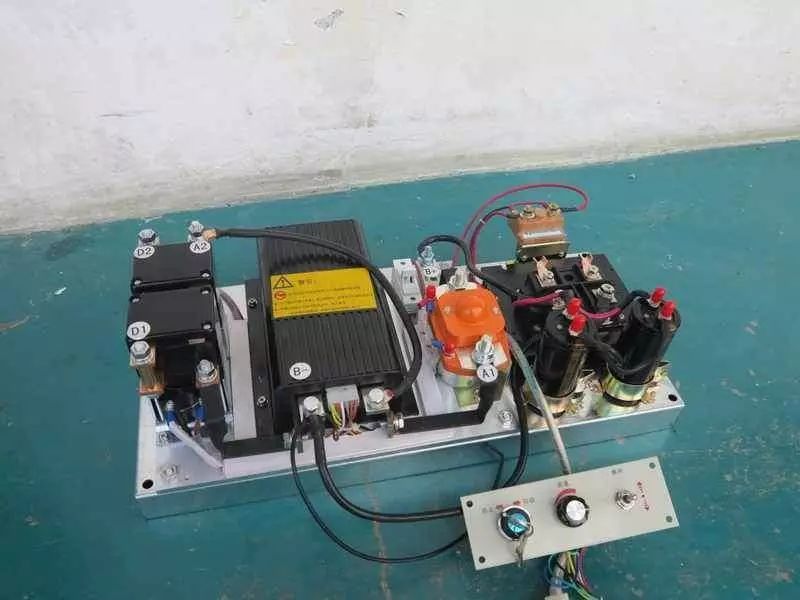
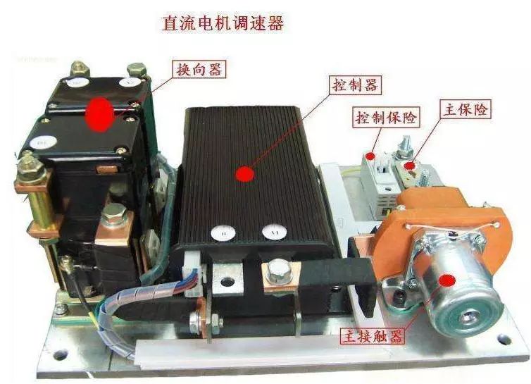
In learning motor drive circuit design, we need to consider what the main factors in order to make a motor drive? For different motors, we should choose the corresponding drive; simply put, that is, the power of the motor should choose a small internal resistance, current allows a large drive, while the power of a small motor, you can use a relatively low-power drive. First, the drive circuit to achieve the function To get a design for a motor project, first consider what functions need to be implemented. Is the motor rotating in one direction or in two directions? For one-way motor drive, just use a high-power transistor or field effect tube or relay to directly drive the motor. When the motor needs to rotate in both directions, you can use an H-bridge circuit composed of 4 power elements or use a double-pole double Throw relay. Motor need not speed? If you do not need to adjust the speed, just use the relay; but if you need to adjust the speed, you can use a transistor, FET and other switching elements to achieve PWM (pulse width modulation) speed. Second, followed by the performance of the motor For the PWM speed-regulating motor drive circuit, there are mainly the following performance indicators. 1) Output current and voltage range, which determines how much power the circuit can drive. 2) Efficiency, high efficiency means not only saving power, but also reducing the heating of the drive circuit. To improve the efficiency of the circuit, we can start from ensuring the switching state of the power devices and preventing the common-state conduction (a problem that may occur in the H-bridge or the push-pull circuit, that is, the two power devices turn on at the same time to short-circuit the power supply). 3) The effect on the control input. The power circuit should have good signal isolation at its input to prevent high voltage and high current from entering the main control circuit. This can be achieved with high input impedance or optocoupler. 4) Impact on the power supply. Common-state conduction can cause a sudden drop in the supply voltage to cause high-frequency power pollution; large currents may cause the ground potential to float. 5) Reliability. The motor drive circuit should do as much as possible, regardless of what kind of control signal, what kind of passive load, the circuit is safe. Third, the motor drive PWM control In general, we design the motor drive more conventional method is to use PWM control. There are two main ways: Integrated motor drive chip In the first method, we use the motor drive module to achieve the braking of the motor by applying voltage across the motor. Advantages of using integrated chip design drive: peripheral circuit is simple, relatively easy to implement, easy to pass through debugging, high failure rate, and low failure rate, but generally such integrated driver chip current drive capability is limited, more commonly used such as: L298P, BTS7960, BTS7971, etc. Wait. MOSFET and dedicated gate driver chip The most typical solution is to use an IR series MOS driver to build the H-bridge circuit drive motor forward and reverse. The main advantages of using the MOS driver design are: large drive capability, strong load capability, and internal resistance of the driver depends on the MOS transistor selected. This makes the product highly customizable and has low product cost. At the same time, there are many disadvantages of MOS, such as: the peripheral circuit is slightly more complicated than the integrated driver, and needs to debug various parameters, such as the selection of the size of the bootstrap capacitor, the selection of the control mode, the parameters of the boost circuit, etc., which also leads to this solution. Many people do not use the reason. In the production of motor drive, first of all I strongly recommend using the MOS bridge method. Although the circuit is a little more complicated, it should be taken for granted as an electronics enthusiast and developer who wants to further research and development. If you want to improve yourself, Discard the integrated motor drive first!
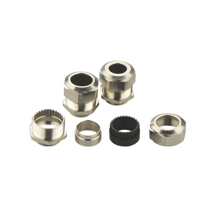
The cable Glands is also called the cable head. After the cable is laid, in order to make it a continuous line, each section of the line must be connected as a whole, and these connection points are called Plastic Cable Glands. The Nylon Cable Gland in the middle of the cable line are called intermediate joints, and the PA cable glands at both ends of the line are called terminal heads. The Cable Glands is used to lock and fix the incoming and outgoing lines, and play the role of waterproof, dustproof and shockproof.
Cable Glands,Metal Dust Cap,Impact Cable Gland,Nylon Cable Gland Kunshan SVL Electric Co.,Ltd , https://www.svlelectric.com

Its main function is to make the line unobstructed, keep the cable sealed, and ensure the insulation level of the Cable Glands, so that it can run safely and reliably. If the seal is not good, not only will the oil leak and cause the oil-impregnated paper to dry up, but also moisture will invade the inside of the cable, reducing its insulation performance.
