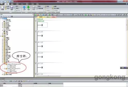
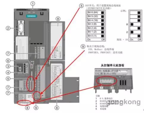
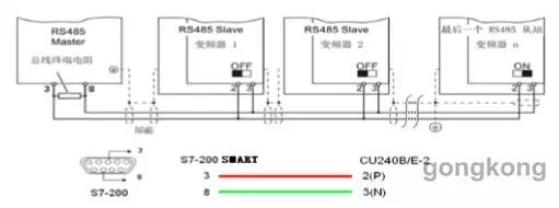
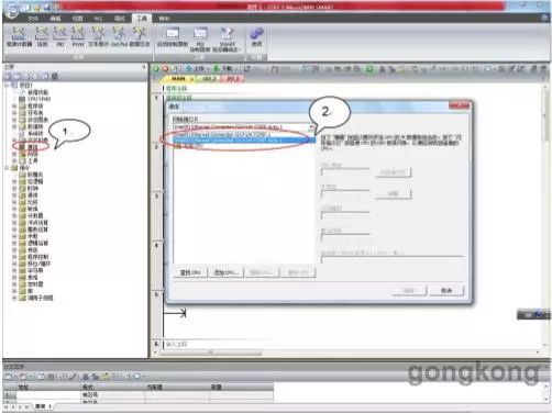
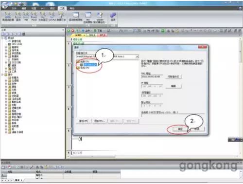
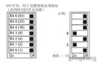
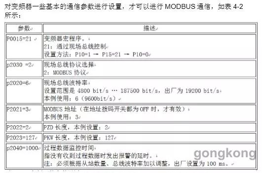
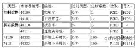
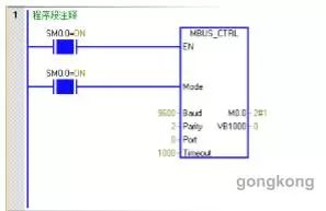
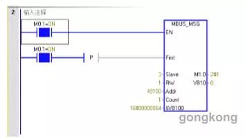
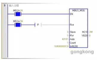
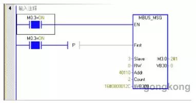
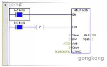
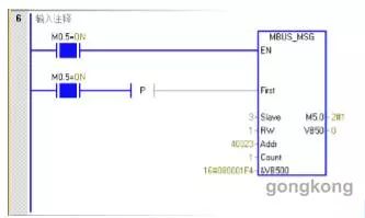
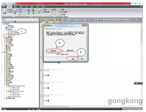
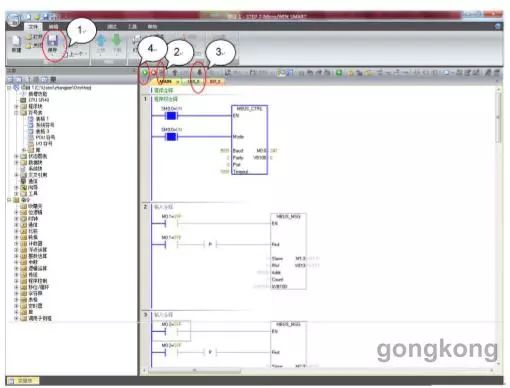
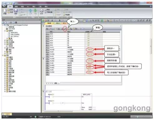
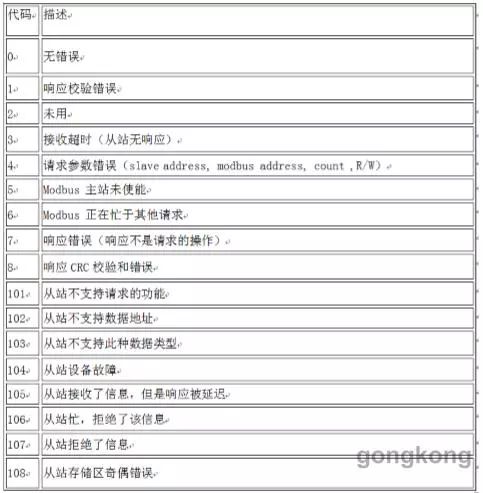
1, system configuration 1.1 Software Install Step7 Micro/Win SMART software (including Modbus protocol library) PC, in this case Step7 Micro-Win SMART V2.0. 1.2 Hardware G120 is equipped with one inverter of CU240E-2 control unit, one asynchronous motor, one S7-200 SMART PLC, one standard DRIVE-CLIQ cable, and one twisted shielded cable. In this example, the G120 control unit CU240E-2 firmware version V4.6 is used. Note: Before creating a project using MicroWin software, confirm that the Modbus library file already exists. Figure 1-1 S7-200 SMART interface 2, hardware wiring 2.1 CU240E-2 control unit interface CU240E-2 control unit terminal block diagram shown in Figure 2-1, RS485 interface at the bottom of the control unit, a total of five terminals, including from left to right, 2 terminals for RS485P, 3 terminals for RS485N, these two terminals for Transmission and reception of communication data. Figure 2-1 Control Unit Terminal Diagram 2.2 G120 and S7-200 SMART wiring Figure 2-2 Connection Diagram of PLC and Controller The S7-200 SMART serves as the Modbus communication master station. The connection between the communication port and the inverter slave station is shown in Figure 2-2. Terminating resistors are required at the beginning and end of the communication network. For the S7-200 SMART, a resistor with a resistance of 120 ohms is required between terminals 3 and 8 of the communication port. For the inverter, turn the CU240E-2 terminating resistor dial switch at the end of the communication network to the ON position (position in Figure 2-1, reference 9); in the middle position of the CU240E-2, the terminating resistor dial switch must be dialed To the OFF position. In this example, the S7-200 SMART uses the CPU's own communication port and frequency converter for communication. 3, communication settings 3.1 Setting up the communication interface This routine uses the PLC Ethernet interface and the DRIVE-CLIQ cable to set up the communication interface, as shown in Figure 3-1 below. The first step: Double-click "Communication" to bring up the "Communication" settings window; Step 2: Select the network interface card and set it to "ICP/IP.AUTO.1". The system will automatically retrieve the CPU. Figure 3-1 Setting Communication Interface 3.2 Establishing a connection between PC and PLC Select "Network Interface" to automatically search for the CPU, as shown in Figure 3-2. Step 1: After searching for the CPU, select the searched CPU and click on the "IP address" of the CPU. Step 2: Click the "OK" button to complete the network connection. Figure 3-2 Establishing an S7-200 CPU and Controller Connection 4th, the frequency changer parameter establishment 4.1 Inverter address setting The Modbus communication address of the inverter can be set via the bus address dial switch on the control unit, as shown in Figure 4-1. When the position of the address dial switch is OFF, it can also be set by parameter P2021. (Note: After changing the address, it will take effect after re-power on) Figure 4-1 Address Switch Settings 4.2 Inverter Parameter Settings Set the basic communication parameters of the inverter to enable Modbus communication, as shown in Table 4-2. Table 4-2 Parameter settings of the inverter 4.3 G120 common register description G120 inverter common register introduction, is also the register used in this example, as shown in Table 4-3. For more information on G120 registers, refer to the G120 operating manual. Table 4-3 Description of Registers 5, PLC programming 5.1 Initialization procedure Using the initialization module MBUS_CTRL of the Modbus protocol, the CPU port of the S7-200 SMART is initialized for Modbus master communication as shown in Figure 5-1. Figure 5-1 Initialization Function block description: Note: The function block descriptions here and below only describe the main pin functions in the function block. For unspecified pin functions, refer to the help file of the Step7 Micro-Win SMART V2.0 software. EN Enable: Must ensure every scan cycle is enabled (using SM0.0 Mode: When 1, the Modbus protocol function is enabled; when it is 0, the system PPI protocol is restored. Baud baud rate: The supported communication baud rates are 4800, 9600, 19200, 9600 is set here. Parity check: check mode selection (G120 uses even check) 0 = no check 1 = odd test 2 = even more accurate Port Port: Sets the physical communication port (0 = RS-485 integrated in the CPU, 1 = RS-485 or RS-232 on the optional CM01 signal board). Timeout Timeout: The time in milliseconds that the master waits for the slave to respond. The typical setting is 1000 milliseconds (1 second). The allowable setting range is 1-32767. Note: This value must be set large enough to ensure that the slave has a time response. Done done bit: initialization is complete, this bit is automatically set to 1. Error: Initialization error code. 5.2 Master Read and Write Function Blocks 5.2.1 Write Control Word Figure 5-2 Write Control Word Function block description: Note: The function block descriptions here and below only describe the main pin functions in the function block. For unspecified pin functions, refer to the help file of the Step7 Micro-Win SMART V2.0 software. EN enable: Only one read/write function (namely MBUS_MSG) can be enabled at a time. Note: The G120 only operates on one holding register at the same time for the write instruction; the read instruction allows a maximum of 125 holding registers at the same time. First read and write request bits: Each new read and write request must use a pulse trigger. Slave slave station address: Selectable range 1-247 RW request method: 0=read, 1=write Count data number: the number of data communications (number of bits or words). Note: The maximum amount of data that the Modbus master can read/write is 120 words (meaning each MBUS_MSG instruction). DataPtr data pointer: If it is a read instruction, the read data is put into this data area; 2. If it is a write instruction, the written data is placed in this data area. Done done bit: Read and write function complete bit. Error error code: The error code is valid only when the Done bit is 1. Commonly used control words: 047E: Operational Preparation 047F: Forward start 0C7F : Reverse start 04FE: fault confirmation 5.2.2 Write Speed ​​Setting Value Figure 5-3 Write Speed ​​Value 5.2.3 Reading Status Words and Speed ​​Actual Values Figure 5-4 Reading Status Word 1 and Speed ​​Actual Value 5.2.4 Reading Ramp Time Figure 5-5 Reading parameters P1120, P1121 5.2.5 Write Ramp Fall Time Figure 5-6 Write parameter P1121 6, allocate storage area Before compiling the program, first allocate the available global V memory address for the Modbus library, as shown in Figure 6-1. The first step: Select "Program block" -> "Library" right click and select "Inventory Storage Area"; Step 2: Click on "Advice Address" and select the address of V memory; Step 3: Click "OK" to exit. Figure 6-1 Allocate storage area 7, the debugger After program editing is completed, debug the program, as shown in Figure 7-1 below. The first step: click "Save" to save the edited program; Step 2: Click "Compile" to compile the program; Step 3: Click "Download" to download the program to the PLC CPU. Step 4: Click "Run" to start the program. Figure 7-1 Debugger 8, monitor the state table By monitoring the status table, you can modify the change status of the process data and monitoring process data, as shown in Figure 8-1. Figure 8-1 Status table Control word: VW100=16#047F Description The start command has been given. Status word: VW300=16#EF37 For status of the inverter, see r0052. Main set value: VW200=16#1000 Description The speed set value has been given, 16#0-4000 corresponds to the value of 0-P2000. The actual speed value: VW302=16#1000 shows that the actual speed of the motor has run to 375rpm. Ramp-up time: VW400 = 1000. It can be seen from the register list that the calibration coefficient of the 40322 register is 100, so the parameter P1120=1000/100=10. Ramp-down time: VW402=2000, read-down time; VW500=2000, set-down time; VW402=VW500, indicating write command has taken effect. It can be seen from the register list that the scaling factor of the 40323 register is 100, so the parameter P1121=2000/100=20. 9, Modbus error code Done bit: The completion bit of the Modbus function block, used to determine whether the operation of the function block is completed; Error error code: The error code is valid only when the Done bit is 1. Table 9-1 shows the Modbus error codes and their meanings. Table 9-1 Modbus Error Code Table Customized Reserch And Develop
A report on Lithium Iron Phosphate (LiFePO4) Battery Market has been added by Kenneth Research into its market research repository. The report provides an extensive analysis of the market by determining the relationship between the dependent and independent variables through correlation and regression for the forecast period, i.e., 2021 2025. The report on Lithium Iron Phosphate (LiFePO4) Battery Market further provides the supply and demand risks associated with the growth of the market, and consists of macro-economic indicators that are contributing to the market growth. The market is thriving on account of the growing trade on fuel worldwide, backed by the rising demand for energy from the end-users.
According to the statistics by the World Bank, exports of fuel increased from 12.91% of merchandise exports in 2001 to 14.25% of merchandise exports in 2018. Additionally, imports of fuel registered a growth by 1.28x between the years 2001 and 2018. In 2001, the import of fuel was 10.30% of merchandise exports whereas in 2018, it was 13.19% of merchandise exports. On the other hand, the increasing focus of the players in the energy and power industry to lower their cost of operations so as to enhance their profitability, is also anticipated to contribute to the market growth. The natural gas rents, which is defined as the difference between the total cost of production of natural gas and the production value at world prices, decreased significantly from 0.40% of GDP in 2001 to 0.18% of GDP in 2017. Alternatively, the oil rents, which increased from 1.09% of GDP in 2001 to 1.30% of GDP in 2019, portrays the need amongst the players to enhance their focus in reducing the cost of production of oil.
Customized Reserch And Develop,Lithium Ion Battery,Lithium Car Battery,Lithium Ion Battery Price,Lithium Battery Price Shenzhen Zhifu New Energy Co., Ltd. , https://www.sunbeambattery.com